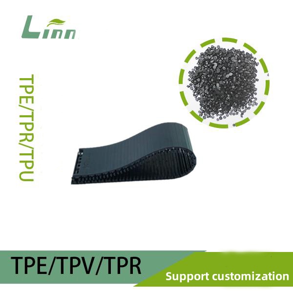
Having spent over a decade in the TPE (thermoplastic elastomer) industry, I’ve seen my fair share of challenges in injection molding, and flow marks are among the most frustrating. These surface imperfections, appearing as wavy or streaky patterns, not only compromise the aesthetics of your product but can also lead to customer complaints or even product rejection. Flow marks are a common issue in TPE molding, but the good news is they can often be resolved by fine-tuning the material formula, process parameters, and equipment setup. In this article, I’ll share my hands-on experience to guide you through practical solutions to eliminate flow marks and achieve a flawless TPE surface finish.

What Are Flow Marks, and Why Do They Occur in TPE Molding?
Flow marks are visual defects on the surface of molded parts, resembling ripples or streaks left by uneven material flow. TPE’s unique viscoelastic properties make it more prone to flow marks than traditional plastics. The root causes typically include:
Material Flowability: TPE’s flow characteristics depend on its base resin (e.g., SEBS or SBS), plasticizers (e.g., white oil), and fillers. Poor or uneven flow can cause layering in the mold, resulting in flow marks.
Processing Temperature: TPE is temperature-sensitive. If the temperature is too low, the material may not fully melt; if too high, it can degrade or form bubbles, both contributing to flow marks.
Mold Design: Issues like improper gate placement, inadequate venting, or rough mold surfaces can disrupt material flow, leading to defects.
Injection Speed and Pressure: Excessively fast injection speeds or insufficient pressure can cause uneven filling, manifesting as flow marks.
Environmental Factors: High humidity or moisture in the material can also trigger surface imperfections.
I recall a project where a client struggled with persistent flow marks on TPE plug components. After investigating, we found the mold’s gate design was suboptimal, the processing temperature was too low, and the formula had an excessively high white oil content. By addressing these issues systematically, we eliminated the flow marks, boosting the product pass rate by 15%. This experience taught me that tackling flow marks requires a holistic approach involving material, process, and mold optimization.

How to Adjust TPE Molding to Eliminate Flow Marks?
Drawing from years of trial and error, I’ve outlined several actionable strategies to address flow marks in TPE injection molding. Let’s dive in.
1. Optimize the TPE Material Formula
The TPE formula directly impacts its flow behavior and surface quality. Here are key adjustments to consider:
Choose High-Flow SEBS: SEBS is a common TPE base resin. Opt for high-molecular-weight, high-flow SEBS (e.g., Kraton G series, see Kraton’s website) to enhance mold filling and reduce flow marks.
Adjust White Oil Content: White oil, a common plasticizer, affects TPE’s softness and flow. Too much (>40%) makes the material overly soft and prone to layering; too little (<20%) increases viscosity, hindering flow. Aim for a 30%-35% white oil content and use low-volatility oils to minimize surface defects.
Reduce Filler Content: Excessive fillers like calcium carbonate can reduce flowability, increasing flow mark risks. Keep calcium carbonate at 5%-10% and use ultrafine grades (particle size <3 microns) to maintain surface smoothness.
Add Flow Modifiers: Incorporating 0.5%-1% silicone masterbatch or polyolefin-based additives can enhance flow, reducing surface streaks.

2. Fine-Tune Injection Molding Parameters
Process parameters are critical in preventing flow marks. Here’s how to optimize them:
Increase Molding Temperature: TPE typically melts at 180-220°C. If the temperature is too low, incomplete melting can cause flow marks. Set the barrel temperature to 190-210°C and mold temperature to 30-50°C. Be cautious, as excessively high temperatures may degrade the material, so test based on your formula.
Optimize Injection Speed: High injection speeds can create turbulence, leading to flow marks, while slow speeds may cause incomplete filling. Use multi-stage injection: start with low speed (20%-30%) for initial filling, then gradually increase to 50%-70% for the remainder.
Extend Holding Time: Increasing holding time (e.g., 5-10 seconds) ensures the material fully fills the mold, minimizing surface defects.
Control Cooling Time: Insufficient cooling can prevent proper material setting, exacerbating flow marks. Set cooling time to 10-15 seconds, adjusting based on part thickness and mold design.

3. Enhance Mold Design
Mold design plays a significant role in flow mark formation. Consider these improvements:
Optimize Gate Placement: Position gates in thicker sections or less visible areas, avoiding thin-walled regions. Side gates or pin gates are preferable for TPE over direct gates.
Improve Venting: Poor venting traps air in the mold cavity, contributing to flow marks. Add 0.01-0.02mm vent slots at parting lines or cavity ends.
Polish Mold Surfaces: Rough mold surfaces impede material flow, increasing flow mark risks. Polish molds to a surface roughness of Ra 0.2-0.4 or apply a Teflon coating to reduce friction.
Enlarge Runner Dimensions: Narrow runners increase flow resistance. Use main runners with a diameter of 4-6mm and sub-runners at 2-3mm.
4. Ensure Proper Material Storage and Pre-Processing
TPE is hygroscopic, and moisture can cause bubbles or flow marks during molding. Follow these steps:
Dry the Material: Dry TPE pellets at 80°C for 2-3 hours before molding to ensure moisture content is below 0.1%.
Store Properly: Keep TPE in a cool, dry environment to avoid moisture absorption or degradation.
Verify Material Quality: Check for impurities or degradation in TPE pellets. If issues persist, consider switching batches or suppliers.

5. Maintain and Inspect Equipment
Injection molding equipment performance can influence flow marks. Here’s what to do:
Inspect Screw and Barrel: Worn screws or contaminated barrels can cause uneven melting. Clean the barrel regularly and ensure the screw surface is smooth.
Calibrate Pressure Systems: Verify that the machine’s pressure control is precise, as fluctuations can lead to uneven filling.
Upgrade Equipment: If your machine is outdated, consider investing in one with advanced temperature and pressure control for better consistency.
TPE Flow Mark Adjustment Reference Table
To help visualize the adjustments, I’ve created a table summarizing process and formula recommendations for different scenarios:
|
Parameter |
Low Flow Mark Risk (High Flow) |
Moderate Flow Mark Risk (Balanced) |
High Flow Mark Risk (Cost-Driven) |
|---|---|---|---|
|
SEBS Type |
High-molecular-weight, high-flow |
Medium-molecular-weight |
Low-molecular-weight |
|
White Oil (wt%) |
30-35% | 35-40% | 40-45% |
|
Calcium Carbonate (wt%) |
5-8% | 8-12% | 12-15% |
|
Silicone Masterbatch (wt%) |
0.8-1.2% | 0.5-0.8% | 0-0.5% |
|
Barrel Temperature (°C) |
200-220 | 190-210 | 180-200 |
|
Mold Temperature (°C) |
40-50 | 30-40 | 20-30 |
|
Injection Speed |
Multi-stage (low start) |
Medium |
High |
|
Holding Time (seconds) |
8-10 | 5-8 | 3-5 |
|
Application |
Premium products requiring smooth surfaces |
General products balancing cost and quality |
Low-cost products prioritizing affordability |
Note: These parameters are guidelines. Adjustments should be tested based on your equipment, mold, and product specifications.
Real-World Case Study
Last year, I worked with a wire plug manufacturer struggling with noticeable flow marks on their TPE parts, which hurt the product’s appearance. After on-site analysis, we identified three culprits:
Material Issue: The formula contained 45% white oil, making the material overly fluid and prone to layering during filling.
Process Issue: The barrel temperature was too low (175°C), causing incomplete melting, and the injection speed was too high, creating turbulence.
Mold Issue: The direct gate was positioned near a thin-walled section, and venting was inadequate.

We implemented the following solutions:
Reduced white oil to 35% and added 0.8% silicone masterbatch to improve flow.
Raised the barrel temperature to 205°C, set the mold temperature to 45°C, and adopted multi-stage injection (30% speed initially, 60% later).
Modified the mold to use a pin gate, added 0.015mm vent slots, and polished the mold surface to Ra 0.3.
These changes virtually eliminated flow marks, significantly improving surface smoothness, and the client was thrilled with the results. This case reinforced that addressing flow marks requires a comprehensive strategy, as isolated fixes often fall short.
Additional Tips to Keep in Mind
Beyond the main adjustments, here are some often-overlooked details:
Conduct Regular Trials: Test small batches whenever switching TPE batches or molds to ensure parameters are compatible.
Document Parameters: Maintain a detailed log of process settings for traceability and future optimization.
Train Your Team: Ensure operators understand TPE molding nuances to avoid errors that could cause flow marks.
Collaborate with Suppliers: If flow marks persist, the material quality may be inconsistent. Discuss molecular weight distribution or additive stability with your supplier.

Frequently Asked Questions
Q1: What if flow marks only appear in specific areas?
A: Localized flow marks often stem from mold design or uneven filling. Check if the gate is near thin-walled sections, optimize venting, and try multi-stage injection with a slower initial speed. Also, ensure mold temperature is consistent to prevent uneven cooling.
Q2: Raising the temperature reduced flow marks but caused bubbles. What now?
A: Bubbles may result from moisture or material degradation. Dry TPE at 80°C for 2-3 hours before molding and slightly lower the barrel temperature (e.g., from 220°C to 210°C). Verify that mold venting is adequate.
Q3: How can low-cost TPE formulas avoid flow marks?
A: Low-cost formulas often have higher filler content, reducing flowability. Keep calcium carbonate below 10%, add 0.5% silicone masterbatch, and raise mold temperature above 40°C to improve filling.
Q4: Flow marks are gone, but surface gloss is reduced. How do I fix this?
A: Lower gloss may result from insufficient mold polishing or excessive fillers. Ensure mold roughness is Ra 0.2-0.4 and reduce calcium carbonate to 5%-8%. For higher gloss, consider adding a small amount of transparent SEBS.
Closing Thoughts
Flow marks in TPE injection molding can be a tough nut to crack, but with targeted adjustments to the material formula, process settings, and mold design, you can achieve smooth, defect-free surfaces. Every step—material selection, temperature control, and mold optimization—plays a pivotal role. I hope this guide equips you with the tools and confidence to tackle flow marks head-on. If you’re facing specific challenges in your production line, feel free to reach out. I’m always eager to share insights and help you create products that shine in both quality and appearance!