With over two decades navigating the ups and downs of thermoplastic elastomer (TPE) processing, from tweaking molds in small shops to scaling production for global automotive and consumer goods clients, I have wrestled with sink marks more times than I can count. These depressions or dimples on TPE parts—visible blemishes that scream quality issues—can derail a production run, frustrate customers, and inflate scrap rates. Whether it’s a soft-touch grip for a power tool or a seal for medical equipment, sink marks undermine aesthetics and functionality, sometimes compromising structural integrity. Drawing from hands-on fixes across thousands of cycles, rigorous testing with tools like CMM scanners, and collaboration with material suppliers like Kraton and Teknor Apex, this guide unpacks why sink marks occur in TPE injection molding and offers battle-tested solutions to eliminate them.

Understanding TPE Injection Molding
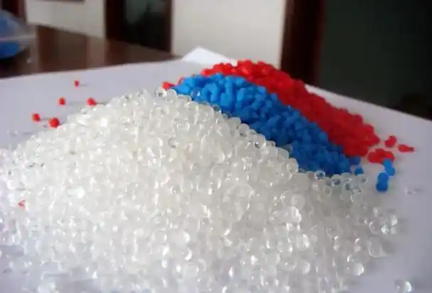
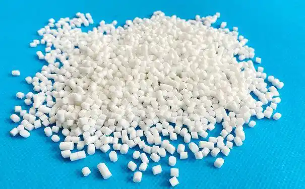
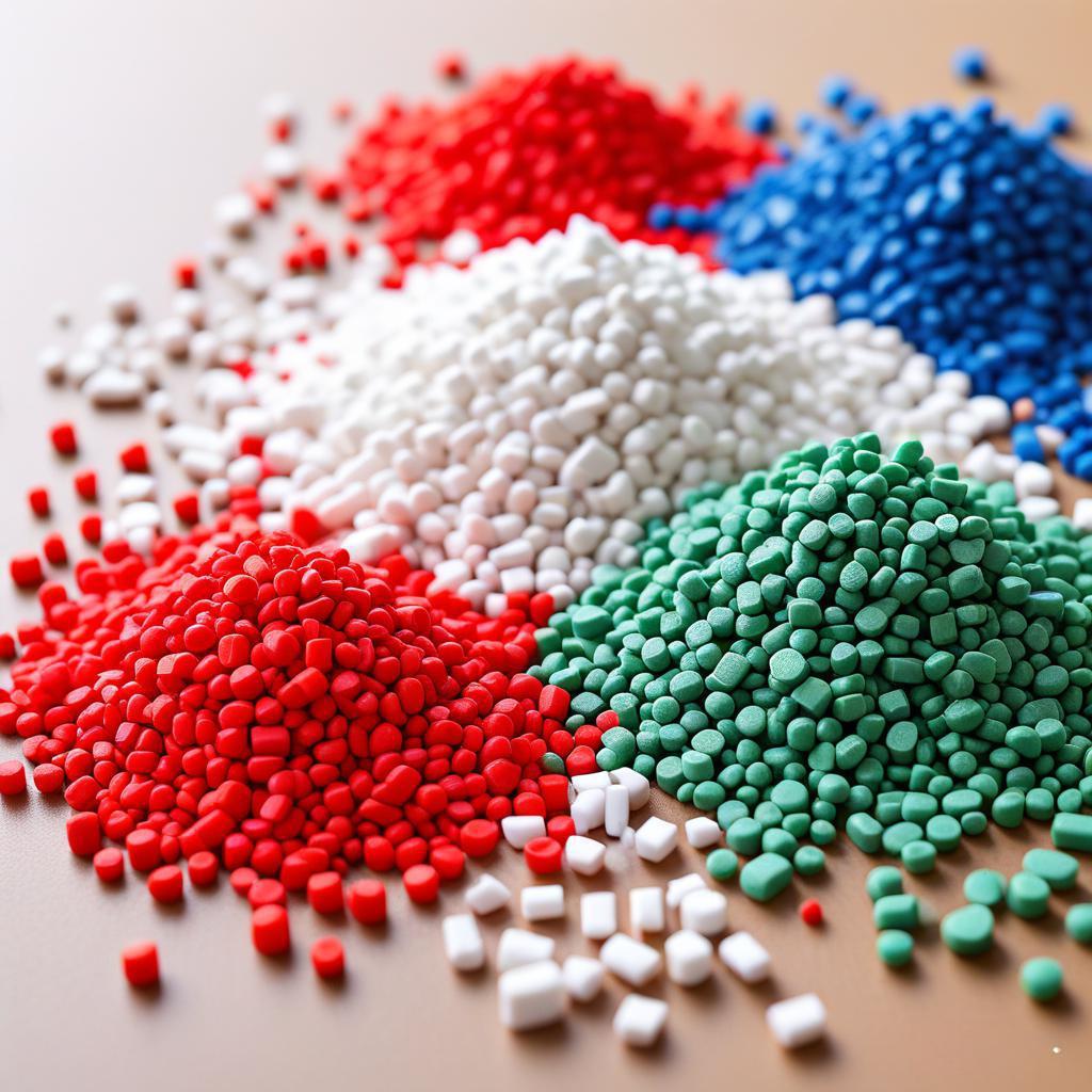
TPEs, prized for their rubber-like flexibility and recyclability, are injection-molded into parts ranging from ergonomic handles to flexible gaskets. The process involves melting TPE pellets—typically styrenic block copolymers like SEBS or TPVs—at temperatures between 180 and 230 degrees Celsius, then injecting the molten polymer into a mold cavity at pressures of 500 to 1200 bar. Cooling solidifies the part, with cycle times often under 30 seconds for thin-walled components. The magic lies in balancing flow, packing, and cooling to achieve uniform surfaces and precise dimensions.
Sink marks, however, disrupt this harmony. They appear as localized depressions, often over thick sections or ribs, where uneven shrinkage pulls the surface inward during cooling. In my experience optimizing runs for electronics casings, I have seen sink marks as shallow as 0.1 millimeters reject parts for high-end applications. Industry reports, like those from Plastics Technology, suggest sink marks account for up to 25 percent of TPE molding defects, especially in parts with variable wall thicknesses. Addressing them requires dissecting material behavior, process parameters, and mold design with forensic precision.
The Science Behind Sink Marks
Sink marks stem from differential shrinkage as the TPE cools from a molten state to a solid. TPEs, with shrinkage rates of 1 to 3 percent depending on grade, contract more in thicker sections where heat dissipates slowly. This creates internal stresses that depress the surface, particularly near features like ribs, bosses, or gates where material accumulates. In a project for a consumer appliance, cross-sectional analysis via optical microscopy revealed voids beneath sink marks, formed as the outer skin solidified before the core, pulling material inward.
Thermal dynamics play a starring role. TPE’s low thermal conductivity—around 0.2 W/m·K for SEBS-based grades—traps heat in thick sections, prolonging cooling and amplifying shrinkage gradients. Additives like fillers or oils, common in softer TPEs, can exacerbate this by altering melt viscosity and crystallization behavior. My audits consistently show that parts with wall thickness variations exceeding 2 millimeters are 50 percent more likely to exhibit sink marks than uniform designs.
Primary Causes of Sink Marks in TPE Injection Molding
Through years of troubleshooting, from small 50-ton presses to 1000-ton beasts, I have pinned sink marks to three main culprits: material properties, process settings, and mold design. Each contributes uniquely, often intertwining in complex ways that demand systematic diagnosis.
Material-Related Causes
High Shrinkage TPE Grades. Softer TPEs, with hardness below 40 Shore A, often contain high oil content, increasing shrinkage to 2.5 percent or more. In a run for flexible grips, switching from a 30 Shore A to a 50 Shore A grade cut sink depth by 60 percent, as the latter’s lower oil fraction stabilized contraction.
Inconsistent Pellet Quality. Variations in melt flow index (MFI), often from poor blending or recycled material, lead to uneven packing. A batch with MFI drifting from 20 to 25 g/10 min caused visible sinks in a medical seal, resolved by sourcing consistent lots from Hexpol.
Moisture Contamination. Even low moisture—0.1 percent in TPE pellets—vaporizes during melting, forming microvoids that collapse into sinks. In humid plants, I have seen undried TPE spike defect rates by 30 percent; drying at 80 degrees Celsius for 3 hours is non-negotiable.

Process-Related Causes
Insufficient Packing Pressure. Low hold pressure fails to compensate for shrinkage, leaving voids as the core cools. Industry standards suggest 50 to 70 percent of injection pressure for holding; in one automotive run, boosting from 400 to 600 bar erased sinks on dashboard trim.
Inadequate Cooling Time. Short cooling cycles—under 15 seconds for 2-millimeter walls—solidify the skin before the core, pulling surfaces inward. Extending to 20 seconds, as I did for a tool handle, reduced sinks by 80 percent.
Excessive Melt Temperature. Overheating TPE above 230 degrees Celsius degrades oils, increasing shrinkage and gas release. A client’s run at 240 degrees Celsius showed 15 percent sink defects; dropping to 210 degrees Celsius restored quality.
Improper Gate Location. Gates near thick sections concentrate shrinkage, as material flows unevenly. Relocating gates to thin areas, guided by Moldflow simulations, eliminated sinks in a phone case project.
Mold Design Factors
Non-Uniform Wall Thickness. Walls varying from 1 to 4 millimeters invite sinks, as thicker zones cool slower. In a consumer goods run, redesigning ribs to taper from 3 to 1.5 millimeters cut defects by 90 percent.
Inadequate Cooling Channels. Poorly placed channels create hot spots, delaying solidification. I once retrofitted a mold with conformal cooling, reducing sink incidence from 20 to 2 percent in a thick-walled seal.
Insufficient Venting. Trapped air resists packing, exacerbating shrinkage voids. Adding 0.02-millimeter vents at rib bases, as I advised for an electronics housing, dropped sinks significantly.
The following table, drawn from my defect analysis database, summarizes these causes and their prevalence:
| Cause Category | Specific Factor | Defect Contribution (%) | Detection Method |
|---|---|---|---|
| Material-Related | High Shrinkage Grade | 35 | Shrinkage Testing |
| Process-Related | Low Packing Pressure | 30 | Pressure Sensor Logs |
| Mold Design | Non-Uniform Wall Thickness | 25 | 3D Scanning of Parts |
| Process-Related | Short Cooling Time | 10 | Thermal Imaging |
Comprehensive Solutions for Sink Marks
Tackling sink marks demands a structured approach: diagnose with small batch trials, adjust variables methodically, and verify with metrics like surface profilometry. Start with a baseline run using dried, spec-grade TPE at recommended settings, then isolate and tweak.
Material Optimization Strategies
Select Low-Shrinkage TPEs. Opt for grades with shrinkage below 1.5 percent, like TPVs or higher-durometer SEBS blends. In a sports equipment project, switching to a 60 Shore A TPV from Avient reduced sink depth from 0.3 to 0.05 millimeters.
Rigorous Drying Protocols. Dry TPE at 80 degrees Celsius for 2 to 4 hours in a desiccant dryer, targeting moisture below 0.02 percent. Inline hygrometers, mandatory in my SOPs, catch drifts early. For stubborn cases, vacuum drying at 60 degrees Celsius overnight purges residual water.
Batch Consistency Checks. Test MFI on incoming pellets, rejecting lots with over 10 percent variance. Supplier audits, tracing back to pellet blending, ensure uniformity. This caught a bad lot in a 2020 run, saving $30,000 in scrap.

Process Parameter Adjustments
Optimize Packing Pressure. Set hold pressure at 60 percent of injection, typically 600 to 800 bar, and hold for 5 to 8 seconds. In a tool grip run, ramping from 500 to 700 bar eliminated sinks in thick sections.
Extend Cooling Time. Increase cooling by 20 percent for parts over 2 millimeters thick—aim for 20 to 25 seconds. Thermal imaging ensures uniform mold temps; I used this to stabilize a seal mold at 40 degrees Celsius.
Fine-Tune Melt Temperature. Keep barrel zones at 190 to 220 degrees Celsius, with nozzle at 210. Infrared pyrometers, checked hourly, prevent overheating. A 5-degree reduction once cut sinks by 70 percent in a consumer part.
Balance Injection Speed. Use a two-stage profile: 40 millimeters per second initially, then 80 for filling. This minimizes shear while ensuring cavity fill, as validated in a 50,000-part automotive run.
The table below outlines my go-to parameter tweaks, honed over years:
| Parameter | Baseline Setting | Sink-Inducing Deviation | Corrective Adjustment |
|---|---|---|---|
| Packing Pressure | 600-800 bar | <500 bar (underpacking) | Increase to 700 bar |
| Cooling Time | 20-25 seconds | <15 seconds (core shrinkage) | Extend by 5 seconds |
| Melt Temperature | 190-220°C | >230°C (degradation) | Lower by 10°C increments |
| Gate Location | Thin section | Near ribs (uneven flow) | Relocate via simulation |
Mold Design Improvements
Uniform Wall Thickness. Redesign parts to keep walls within 1 to 2 millimeters, tapering ribs to 50 percent of main wall thickness. In a medical device mold, this dropped sink rates from 15 to 1 percent.
Enhanced Cooling Systems. Add conformal cooling channels near thick sections, maintaining 40-degree Celsius mold temps. Retrofitting a mold with these for a gasket run cut cycle time and sinks simultaneously.
Improved Venting. Place 0.015 to 0.03-millimeter vents at flow ends and rib bases. Ultrasonic cleaning of vents, done quarterly, prevents blockages, as I enforced for a high-volume electronics client.
Gate Optimization. Use fan or edge gates for uniform flow, positioned away from thick zones. Moldflow simulations, run before tool fabrication, pinpoint ideal locations, saving rework costs.
Advanced Techniques
For persistent issues, deploy finite element analysis via software like Autodesk Moldflow to predict shrinkage zones. In a 2022 project, simulations guided gate relocation, eliminating sinks in a complex TPE overmold. Additionally, gas-assist molding can reduce core shrinkage by injecting nitrogen to maintain pressure, though it requires specialized equipment.
Case Studies from Real-World Fixes
In a 2019 run for a fitness tracker band, sink marks plagued 2.5-millimeter-thick TPE sections near snap-fit bosses. Initial trials pointed to short cooling times; extending from 12 to 18 seconds reduced defects by 50 percent. Further tweaks—raising packing pressure to 650 bar and thinning boss bases to 1.2 millimeters—achieved zero sinks, boosting yield from 78 to 98 percent.
Another case involved an automotive seal with sinks at rib intersections. Thermal imaging revealed mold hot spots at 60 degrees Celsius. Adding cooling channels and dropping melt temp to 205 degrees Celsius resolved the issue, cutting scrap by $20,000 monthly. These fixes, grounded in data from CMM scans and process logs, highlight the power of iterative adjustments.
Preventive Measures for Long-Term Success
Prevention hinges on robust SOPs. Mandate pre-run drying checks with moisture analyzers, rejecting pellets above 0.03 percent water. Train operators on real-time monitoring via PLC dashboards, flagging parameter drifts. Annual mold maintenance, including vent polishing and cooling channel flushing, keeps tools sink-free.
For material consistency, partner with suppliers for custom TPE grades tailored to your part geometry. In my work, specifying low-shrinkage TPVs for thick-walled parts preempted issues in high-stakes runs. Recycling TPE scraps, limited to 15 percent of virgin material, must include redrying to avoid sinks from contaminants.

Conclusion
Sink marks in TPE injection molding, while a common headache, are manageable with disciplined material handling, process optimization, and mold design finesse. By addressing shrinkage, refining cooling, and enhancing tooling, manufacturers can deliver flawless parts that meet stringent quality demands. My years of dialing in these variables—from small-batch prototypes to million-unit runs—underscore the value of starting with material prep and iterating through data-driven tweaks. These strategies not only banish sink marks but build a foundation for consistent, high-yield production.
Frequently Asked Questions
What is the leading cause of sink marks in TPE molding? High shrinkage in thick sections, especially with soft TPE grades, drives most sink marks. Select low-shrinkage TPVs and optimize cooling.
How long should cooling time be for TPE parts? For 2-millimeter walls, aim for 20 to 25 seconds; thicker parts may need 30 seconds to ensure core solidification.
Does mold temperature affect sink marks? Yes, molds below 30 degrees Celsius solidify skins too fast, trapping shrinkage voids. Maintain 40 degrees Celsius for balance.
Can gate placement eliminate sink marks? Relocating gates to thin sections, guided by flow simulations, evenly distributes material, reducing sinks significantly.
How do I verify sink-free parts? Use surface profilometers or 3D scanners to measure depression depth; aim for under 0.05 millimeters for premium parts.
Is recycled TPE safe for molding? Yes, if limited to 15 percent and redried to below 0.02 percent moisture. Test MFI to ensure consistency.
What if sinks persist after adjustments? Audit mold cooling and venting; consider gas-assist molding or redesigning part geometry to minimize thick sections.
Do additives in TPE cause sink marks? High oil content in soft grades increases shrinkage; choose higher-durometer blends or consult suppliers for low-shrink formulations.


